
Mình đang thực hành làm quen với FPGA,mình có dùng kit spartan3E(xc3s500) nhưng thấy mấy examp của nó khó quá,mỗi hiển thị lên LCD thối mà mã dài dằng dặc.Có ai đã từng thực tập trên kít này rồi cho mình xin ít ví dụ,project càng tốt,mình cảm ơn!
-
Technical Institutes
Mobile: 0983278725
Email: -
Cũng không khó lắm bạn àh. Nếu bạn dùng microblaze, thực hiện thêm bước add GPIO vào bus OPB, sau đó gán chân vào file .ucf . Đọc GPIO ví dụ của LED do EDK tạo sẵn và làm tương tự cho phần driver LCD là được. Khi nào rãnh mình cùng thảo luận sau nhá. -
Cai ISE 6.2i
Mình co cai ISE 6.2 phien ban download cua xilinx nhung khong hieu sao no cu bao loi nhu the nay(hinh duoi day),moi nguoi chi dum voi!
Minh cung cai ban 8.2i nhung nhieu cho thao tac thay khong giong voi chi dan trong guide voi lai nhieu example ho viet bang 6.2 nen khong doc duoc!Attached FilesTechnical Institutes
Mobile: 0983278725
Email:Comment
-
-
Chắc vấn đề nằm ở chỗ bạn cài 8.2i trước sau đó cài 6.2i mà bản 8.2i chưa hoàn toàn bị xoá sạch, cố gắng dùng các soft clean registry thử xem.Comment
-
Và một điểm cần chú ý là , khi bạn xài EDK 8.2 thì nhất định phải cài ISE 8.2 thì mới có thể khởi động được EDK.
Trong kit SP3E nó đính kèm các đĩa 8.2 tại sao bạn không sử dụng ISE 8.2 mà lại dùng bản 6.2 ???Comment
-
Van de la:minh co dơnload duoc may vi du ve kit spartan3e cua xilinx nhung ho viet toan bang 6.2 nen cac project khong the dung ban 8.2 doc duoc,ma mình lay file nguon .vhd add vao 8.2 thi khi dich bao loi khong tao thanh file .bit duoc,minh muon thu xem ban 6.2 doc va dich nhu the nao hon nua cac tai lieu ho toan huong dan ban 6.2 thoi.Co ban 8.2 ma khong su dung duoc dau qua!Mong moi nguoi chi dan dum,hien minh dang kho khan o cho hien thi LCD.Sao thay ma o cac vi du tren mang dai dang dac vay,vi du nhu doan duoi day?
moi nguoi co the giai thich dum minh doan ma tren khong?Code:////////////////////////////////////// library IEEE; use IEEE.STD_LOGIC_1164.ALL; use IEEE.STD_LOGIC_ARITH.ALL; use IEEE.STD_LOGIC_UNSIGNED.ALL; entity LCD is port( LCD_RS:out std_logic; LCD_RW:out std_logic; LCD_E:out std_logic; clk:in std_logic; SF_D:out std_logic_vector(3 downto 0) ); end LCD; architecture Behavioral of LCD is signal substate,clock,clk1: integer:=0; signal state: integer:=0; begin process(clk) begin clk1<=clk1+1; if(clk1=0) then clock<=clock+1; --WAIT FOR 750000 CLOCK if(state=0 and clock=750000) then state<=1; clock<=0; --WRITE SF_D=0X3 FOR INIATION elsif(state=1) then if(substate=0 and clock=0) then LCD_RS<='1'; LCD_RW<='0'; SF_D<="0000"; Clock<=0; substate<=1; elsif(substate=1 and clock=2) then LCD_E<='1'; Clock<=0; substate<=2; elsif(substate=2 and clock=12) then LCD_E<='0'; substate<=3; Clock<=0; elsif(substate=3 and clock=48) then SF_D<="0011"; Clock<=0; substate<=4; elsif(substate=4 and clock=2) then LCD_E<='1'; Clock<=0; substate<=5; elsif(substate=5 and clock=12) then LCD_E<='0'; substate<=0; state<=2; Clock<=0; end if; --WAIT FOR 2050000 CLOCK elsif(state=2 and clock=205000) then state<=3; clock<=0; --WRITE SF_D=0X3 FOR INIATION elsif(state=3) then if(substate=0 and clock=0) then LCD_RS<='1'; LCD_RW<='0'; SF_D<="0000"; Clock<=0; substate<=1; elsif(substate=1 and clock=2) then LCD_E<='1'; Clock<=0; substate<=2; elsif(substate=2 and clock=12) then LCD_E<='0'; substate<=3; Clock<=0; elsif(substate=3 and clock=48) then SF_D<="0011"; Clock<=0; substate<=4; elsif(substate=4 and clock=2) then LCD_E<='1'; Clock<=0; substate<=5; elsif(substate=5 and clock=12) then LCD_E<='0'; substate<=0; state<=4; Clock<=0; end if; --WAIT 5000 CLOCK elsif(state=4 and clock=5000) then state<=5; clock<=0; --WRITE 0X3 FOR INITIATION elsif(state=5) then if(substate=0 and clock=0) then LCD_RS<='1'; LCD_RW<='0'; SF_D<="0000"; Clock<=0; substate<=1; elsif(substate=1 and clock=2) then LCD_E<='1'; Clock<=0; substate<=2; elsif(substate=2 and clock=12) then LCD_E<='0'; substate<=3; Clock<=0; elsif(substate=3 and clock=48) then SF_D<="0011"; Clock<=0; substate<=4; elsif(substate=4 and clock=2) then LCD_E<='1'; Clock<=0; substate<=5; elsif(substate=5 and clock=12) then LCD_E<='0'; substate<=0; state<=6; Clock<=0; end if; --WAIT 2000 CLOCK elsif(state=6 and clock=2000) then state<=7; clock<=0; --WRITE SF_D=0X2 FOR INITIATION elsif(state=7) then if(substate=0 and clock=0) then LCD_RS<='1'; LCD_RW<='0'; SF_D<="0000"; Clock<=0; substate<=1; elsif(substate=1 and clock=2) then LCD_E<='1'; Clock<=0; substate<=2; elsif(substate=2 and clock=12) then LCD_E<='0'; substate<=3; Clock<=0; elsif(substate=3 and clock=48) then SF_D<="0010"; Clock<=0; substate<=4; elsif(substate=4 and clock=2) then LCD_E<='1'; Clock<=0; substate<=5; elsif(substate=5 and clock=12) then LCD_E<='0'; substate<=0; state<=8; Clock<=0; end if; --WAIT 2000 CLOCK elsif(state=8 and clock=2000) then state<=9; clock<=0; --WRITE FUNCTION SET SD_F = 0X28 elsif(state=9) then if(substate=0 and clock=0) then LCD_RS<='1'; LCD_RW<='0'; SF_D<="0010"; Clock<=0; substate<=1; elsif(substate=1 and clock=2) then LCD_E<='1'; Clock<=0; substate<=2; elsif(substate=2 and clock=12) then LCD_E<='0'; substate<=3; Clock<=0; elsif(substate=3 and clock=48) then SF_D<="1000"; Clock<=0; substate<=4; elsif(substate=4 and clock=2) then LCD_E<='1'; Clock<=0; substate<=5; elsif(substate=5 and clock=12) then LCD_E<='0'; substate<=0; state<=10; Clock<=0; end if; --WAIT 2000 CLOCK elsif(state=10 and clock=2000) then state<=11; clock<=0; --WRITE ENTRY SET SF_D = 0X06 elsif(state=11) then if(substate=0 and clock=0) then LCD_RS<='0'; LCD_RW<='0'; SF_D<="0000"; Clock<=0; substate<=1; elsif(substate=1 and clock=2) then LCD_E<='1'; Clock<=0; substate<=2; elsif(substate=2 and clock=12) then LCD_E<='0'; substate<=3; Clock<=0; elsif(substate=3 and clock=48) then SF_D<="0110"; Clock<=0; substate<=4; elsif(substate=4 and clock=2) then LCD_E<='1'; Clock<=0; substate<=5; elsif(substate=5 and clock=12) then LCD_E<='0'; substate<=0; state<=12; Clock<=0; end if; --WAIT 2000 CLOCK elsif(state=12 and clock=2000) then state<=13; clock<=0; --WRITE DISPLAY ON /OFF SD_F=0X0C elsif(state=13) then if(substate=0 and clock=0) then LCD_RS<='0'; LCD_RW<='0'; SF_D<="0000"; Clock<=0; substate<=1; elsif(substate=1 and clock=2) then LCD_E<='1'; Clock<=0; substate<=2; elsif(substate=2 and clock=12) then LCD_E<='0'; substate<=3; Clock<=0; elsif(substate=3 and clock=48) then SF_D<="1011"; Clock<=0; substate<=4; elsif(substate=4 and clock=2) then LCD_E<='1'; Clock<=0; substate<=5; elsif(substate=5 and clock=12) then LCD_E<='0'; substate<=0; state<=14; Clock<=0; end if; --WAIT 2000 CLOCK elsif(state=14 and clock=2000) then state<=15; clock<=0; --WRITE CLEAR DISPLAY COMMAND SF_D<=0x HAVE TO FIX THIS elsif(state=15) then if(substate=0 and clock=0) then LCD_RS<='0'; LCD_RW<='0'; SF_D<="0000";-- I HAVE FIXED IT Clock<=0; substate<=1; elsif(substate=1 and clock=2) then LCD_E<='1'; Clock<=0; substate<=2; elsif(substate=2 and clock=12) then LCD_E<='0'; substate<=3; Clock<=0; elsif(substate=3 and clock=48) then SF_D<="0001";-- I HAVE FIXED IT Clock<=0; substate<=4; elsif(substate=4 and clock=2) then LCD_E<='1'; Clock<=0; substate<=5; elsif(substate=5 and clock=12) then LCD_E<='0'; substate<=0; state<=16; Clock<=0; end if; --WAIT FOR 82,000 CLOCK elsif(state=16 and clock=82000) then state<=17; clock<=0; --WRITE SET DD RAM ADD SF_D<=0x HAVE TO FIX THIS elsif(state=17) then if(substate=0 and clock=0) then LCD_RS<='0'; LCD_RW<='0'; SF_D<="1000";--IT HAS BEEN FIXED Clock<=0; substate<=1; elsif(substate=1 and clock=2) then LCD_E<='1'; Clock<=0; substate<=2; elsif(substate=2 and clock=12) then LCD_E<='0'; substate<=3; Clock<=0; elsif(substate=3 and clock=48) then SF_D<="0000";-- IT HAS BEEN FIXED Clock<=0; substate<=4; elsif(substate=4 and clock=2) then LCD_E<='1'; Clock<=0; substate<=5; elsif(substate=5 and clock=12) then LCD_E<='0'; substate<=0; state<=18; Clock<=0; end if; --WAIT FOR 2,000 CLOCK elsif(state=18 and clock=2000) then state<=19; clock<=0; --WRITE DD RAM ADD SF_D<=0x HAVE TO FIX THIS elsif(state=19) then if(substate=0 and clock=0) then LCD_RS<='1'; LCD_RW<='0'; SF_D<="0100";--IT HAS BEEN FIXED Clock<=0; substate<=1; elsif(substate=1 and clock=2) then LCD_E<='1'; Clock<=0; substate<=2; elsif(substate=2 and clock=12) then LCD_E<='0'; substate<=3; Clock<=0; elsif(substate=3 and clock=48) then SF_D<="0001";-- IT HAS BEEN FIXED Clock<=0; substate<=4; elsif(substate=4 and clock=2) then LCD_E<='1'; Clock<=0; substate<=5; elsif(substate=5 and clock=12) then LCD_E<='0'; substate<=0; state<=20; Clock<=0; end if; elsif(state=20)then state<=20; clock<=0; end if; elsif(clk1=1) then clk1<=0; end if; end process; end Behavioral; /////////////////////////////////////////Last edited by namqn; 17-09-2007, 18:18.Technical Institutes
Mobile: 0983278725
Email:Comment
-
Đợi hoài mà không ai trả lời dùm sao?Technical Institutes
Mobile: 0983278725
Email:Comment
-
Các file HDL đều tuân theo chuẩn IEEE. Bạn không thấy ở đầu họ dùng thư viện IEEE sao.
Còn về code dài thì tất nhiên rùi. Vì bạn đọc datasheet của LCD, giao thức để giao tiếp với LCD phức tạp chứ có phải đưa dữ liệu ra là nó tự hiển thị cho bạn đâu.Code:library IEEE; use IEEE.STD_LOGIC_1164.ALL; use IEEE.STD_LOGIC_ARITH.ALL; use IEEE.STD_LOGIC_UNSIGNED.ALL;
Bạn đọc kĩ từng bước một sẽ hiểu ngay mà. Code của bạn nên để trong tag code cho dễ đọc nhé.
Thứ 2 là HDL là ngôn ngữ miêu tả phần cứng do đó một project tạo bởi ISE 6.2 phải đọc được ở bản 8.2 chứ. Nếu không được bạn tạo một project và add source các component đó vào.
Chú bạn thành công.Technical sale at WT Microelectronics S'pore
Hỗ trợ dự án sử dụng các hãng Texas Instrument, STMicro, Freescale, Fairchild, International Rectifier, Ublox, Lumiled, Maxim
Liên hệ: 0915.560.511 hoặc ngo.haibac@wtmec.comComment
-
Tui setup project chạy trên ISE 8.2 rồi, không có vấn đề gì cả, bác xem lại thử xem. Các bước thực hiện như sau:
New Project -> Chọn Device -> add VHDL source -> Synthesize -> Constraint, asign pins -> generate programming file.
Cái này làm chơi chơi để hiểu thêm thôi, nên dùng phần điểu khiển firmware để có thể thay đổi hiển thị theo mong muốn.Comment
-
LCD demo cho microblaze
Sau đây là các bước thực hiện LCD demo cho microblaze.
Tool : EDK 8.2
Demo trên board ML403, tuy nhiên vẫn có thể thay đổi chút ít cho board Spartan3E Starter
Hướng dẫn step by step, hình hơi nhiều, chữ thì ít ( lười viết mà) thông cảm nhá.
Chú ý: Vài bước được thông qua ( để mặc định và ấn nút next) thay vì post hình đầy đủ.
----------------------------------------------------------------------
PHAN 1 : Setup hardware
----------------------------------------------------------------------
1> Start XPS 8.2i
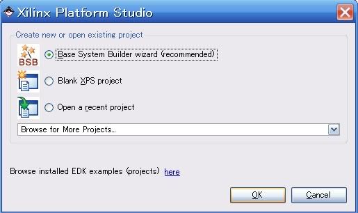
2> Tạo thư mục chứa project
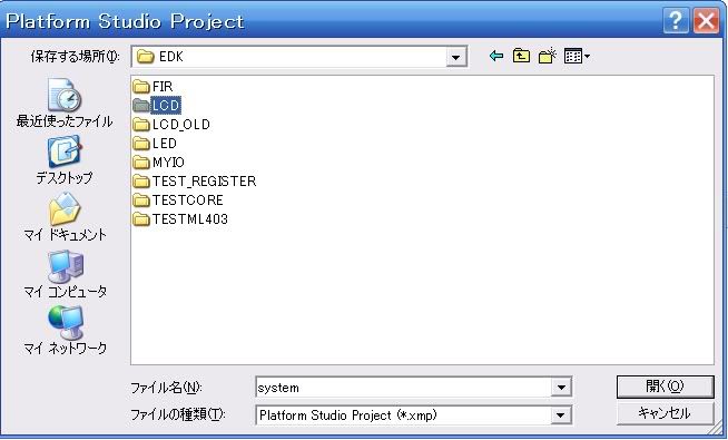
3> Creat new base system

4> Select Board (chú ý: một số board có nhiều revision khác nhau, nên chọn revison thích hợp)

5> Chọn món ăn tùy vào túi tiền
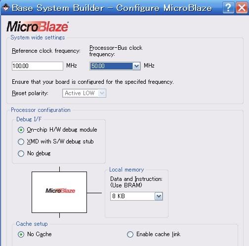
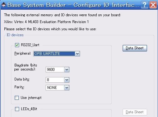


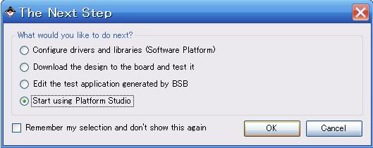 Last edited by kamejoko80; 18-09-2007, 05:04.
Comment
-
LCD demo cho microblaze 2
6> Creat Custom hardware (lcd port)
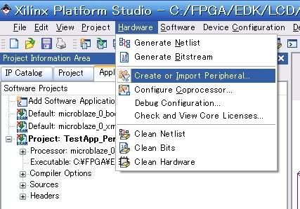
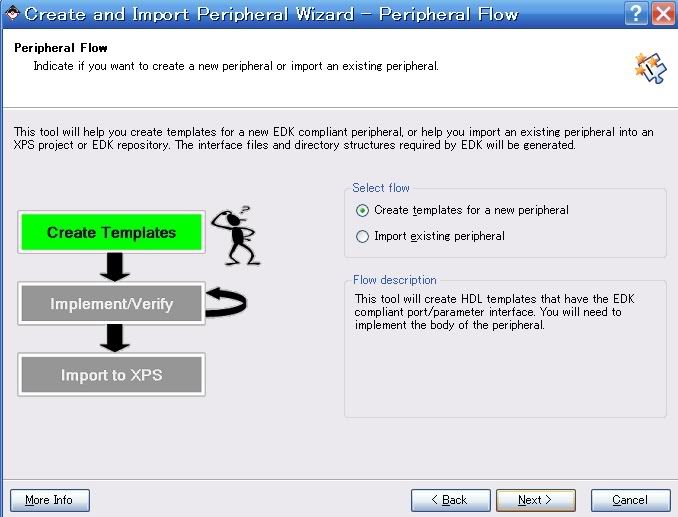

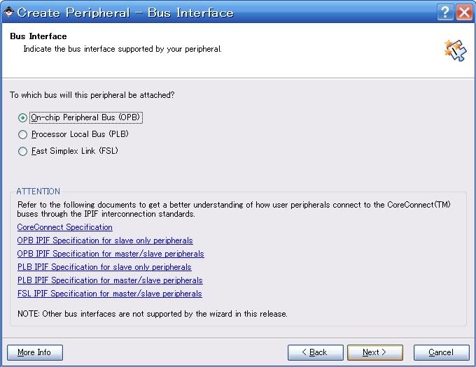
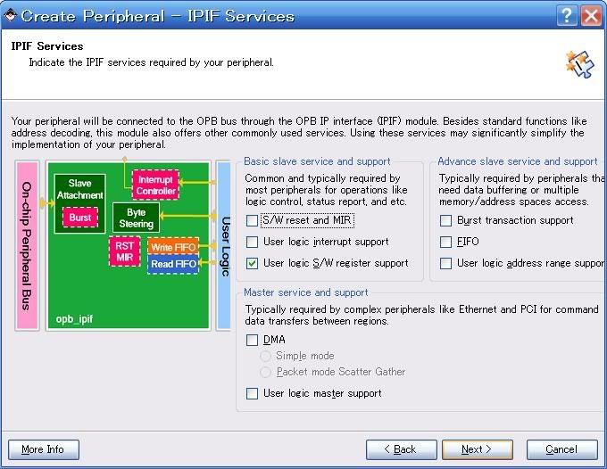

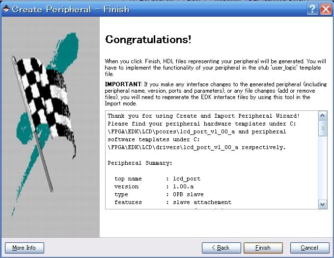
Sau khi hoàn tất các bước trên, XPS tạo ra các file có cấu trúc như sau:
Phần hardware chứa trong thư mục pcores, bao gồm tên (lcd_port) gắn với version hardware chỉ định (lcd_port_v1_00_a)
Phần software chứa trong thư mục drivers (sẽ được trình bày trong phần sau)
 Last edited by kamejoko80; 18-09-2007, 05:01.
Comment
-
LCD demo cho microblaze 3
7> Edit custom hardware
Sau khi thực hiện xong thao tác creat custom peipheral (dùng bus OPB), XPS tạo ra 2 file source vhdl bao gồm name.vhd và user_logic.vhd chứa trong thư mục vhdl
8> Edit user_logic.vhd
goto hàng (khoảng 100) add user port theo hình sau:

XPS tạo thanh ghi "slv_reg0" cho truy xuất với customer ip core, trong trường hợp này ta gán cho port xuất lcd
goto hàng (khoảng 208-209) add code như hình sau

9> Edit lcd_port.vhd
goto hàng (khoảng 119) add user port theo hình sau:

goto hàng (khoảng 388) map port

Xong bước creat , edit customer OPB portComment
-
LCD demo cho microblaze 4
10> Import custom hardware
Trên tool bar : Hardware -> Creat or import peripheral
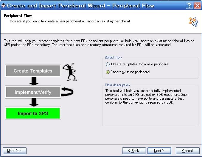
Đặt tên lcd_port

Chọn yes for overwrite

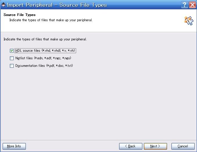
Check radio cho mục file .pao, browse đến đường dẫn thư mục hardware chứa file này

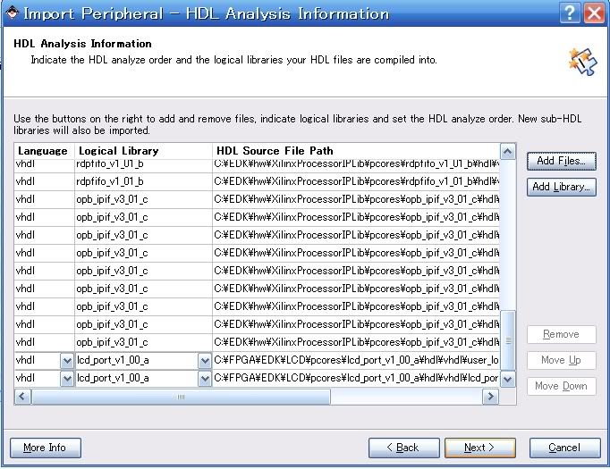
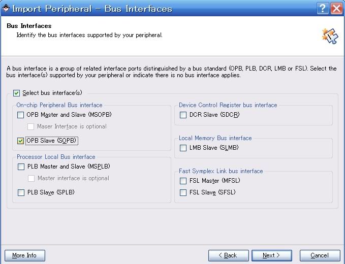
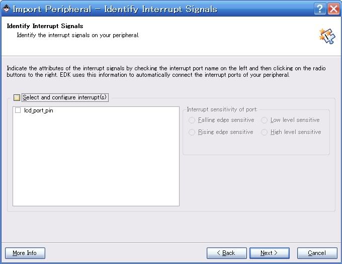
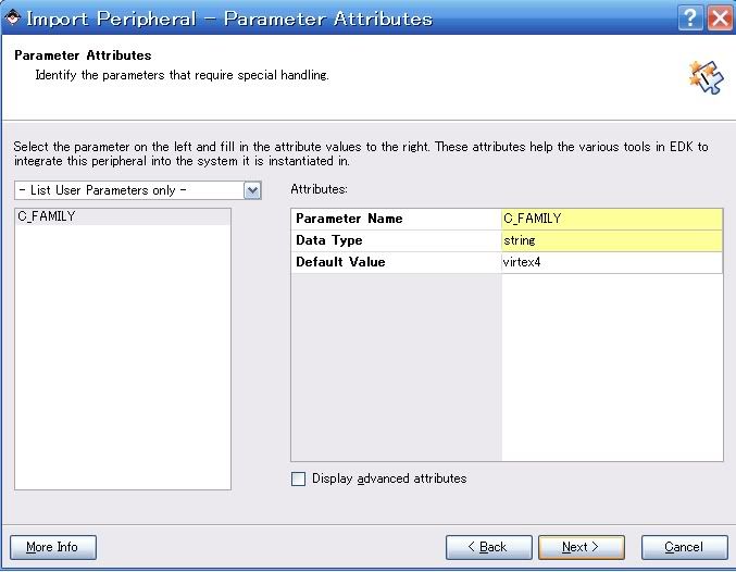
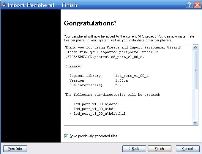
Comment
-
Kamejoko chơi cả Virtex 4 cơ à? Hàng hiệu khủng đây.Comment
-
LCD demo cho microblaze 5
11> Add ipcore vào bus OBP
Trên tab IP Catalog chọn Project Repository, click chuột phải vào lcd_port chọn add IP

Trên mục system assembly view ta thấy custom ip core lcd_port_0 được add vào, lúc này lcd_port_0 chưa thật sự được gắn vào bus OPB, ta thực hiện bước connect vào OPB theo hình sau:
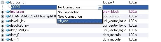
Chọn nút radio của mục port , connection filters chọn all để hiển thị tất cả các đường kết nối.
OPB_clk -> sys_clk_s : system clock source
lcd_port_pin -> Make external
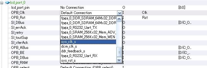

Sau khi kết nối lcd_port_pin với external port, mục trên cùng External Ports xuất hiện đường kết nối lcd_port_0_lcd_port_pin, rename phần tên kết nối phía bên trái để tiện cho việc assign pin constrain.

Chọn nút radio address, trong mục size (kích thước vùng nhớ cho ngoại vi) trong drop list chọn 64K, sau đó chọn Generate Addresses, Xillin tự động tính toán các đường địa chỉ và remap lại cho toàn bộ ngoại vi.
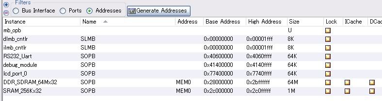
Cuối cùng là bước assign constrain pins cho lcd_port, tùy theo kết nối của các board khác nhau ta có các khai báo gán pins khác nhau.

Tool -> Hardware -> Generate Bitstream. Đến bước này ta có thể thong thả ngồi uống Coca chờ đợi XPS hoàn tất cho phần hardware.
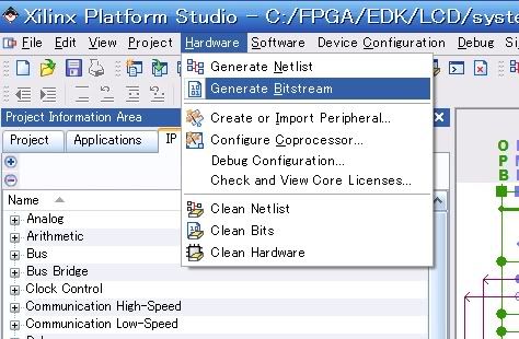
Đuối roài !!!, hôm nay tạm ngưng ở đây, hôm sau trình bày tiếp về phần firmware.Comment


 Tìm hiểu thêm về process

-

-
 Chào các bác kỹ sư nhúng,
Hôm nay mình muốn trao đổi về vấn đề an toàn khi nạp firmware từ xa (FOTA). Khi triển khai hàng trăm thiết bị ở xa, rủi ro lớn nhất là đang cập nhật firmware thì mất điện hoặc rớt mạng giữa chừng khiến...02-10-2026, 15:01

Comment